VRF (Virtual Routing and Forwarding)
In this lesson we’re going to take a look at VRFs (Virtual Routing and Forwarding) and how we can configure them on our Cisco devices.
Exam Topic
4.0 Virtualization
2.2 Configure and verify data path virtualization technologies
2.2.a VRF
Video Overview
Overview
VRFs allow us to have separate virtual routers within a single physical router – in a similar way to how VMs work.
What these virtual routers will do is prevent traffic from one of our VRFs communicating or forwarding traffic to another VRF. Completely segmenting and isolating the traffic.
VRFs are similar to how VLANs work at layer 2, however operate at layer 3 on our OSI model.
By default, without the use of VRFs our routers use a single global routing table that contains all of the routers interfaces and routes learned.
With the use of VRFs, we can separate these our into separate ‘virtual routers’ and complete segment them.
There are two methods of implementing VRFs. Most commonly, VRFs are used for MPLS deployments to seperate and segment customer traffic at the core. As this isn’t covered as part of the CCNP Enterprise ENCOR exam, we’re not going to
be taking a look at this.
Instead, we’ll be looking at VRF-Lite. This is used when we’re using VRFs without MPLS.
Using VRFs within the network provides huge benefits.
Configuration
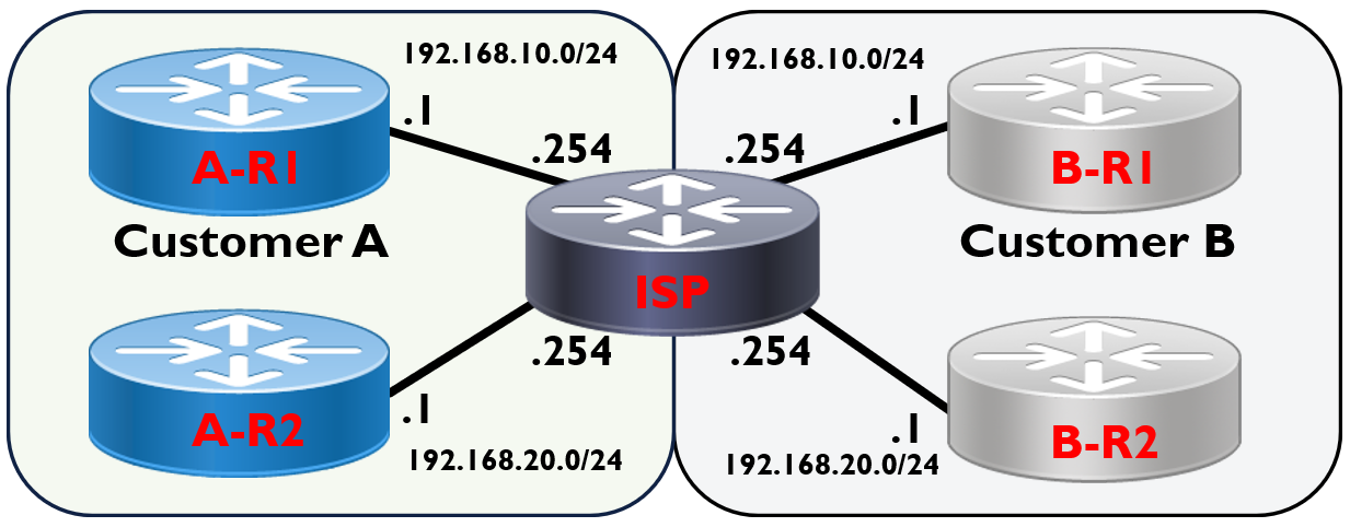
We’ll be using the topology above to configure VRFs on our ISP router. In the example we have two customers (Customer A and Customer B) connected to our ISP. Both of our customers want to use the same IP subnets:
We’ll start by configuring our customer routers:
Customer A Configuration
A-R1#configure terminal
A-R1(config)#interface Serial2/0
A-R1(config-if)#ip address 192.168.10.1 255.255.255.0
A-R1(config-if)#no shutdown
A-R1(config)#ip route 0.0.0.0 0.0.0.0 192.168.10.254
A-R2#configure terminal
A-R2(config)#interface Serial2/0
A-R2(config-if)#ip address 192.168.20.1 255.255.255.0
A-R2(config-if)#no shutdown
A-R2(config)#ip route 0.0.0.0 0.0.0.0 192.168.20.254
Customer B Configuration
B-R1#configure terminal
B-R1(config)#interface Serial2/0
B-R1(config-if)#ip address 192.168.10.1 255.255.255.0
B-R1(config-if)#no shutdown
B-R1(config)#ip route 0.0.0.0 0.0.0.0 192.168.10.254
B-R2#configure terminal
B-R2(config)#interface Serial2/0
B-R2(config-if)#ip address 192.168.20.1 255.255.255.0
B-R2(config-if)#no shutdown
B-R2(config)#ip route 0.0.0.0 0.0.0.0 192.168.20.254
Basic ISP Configuration
We’ll start by configuring our interfaces connecting our ISP to customer A.
ISP#configure terminal
ISP(config)#interface Serial2/0
ISP(config-if)#description Link to A-R1
ISP(config-if)#ip address 192.168.10.254 255.255.255.0
ISP(config-if)#no shutdown
!
ISP(config-if)#interface Serial2/1
ISP(config-if)#description Link to A-R2
ISP(config-if)#ip address 192.168.20.254 255.255.255.0
ISP(config-if)#no shutdown
Now that’s been completed, let’s try and configure our interfaces connecting our ISP to customer B.
ISP(config-if)#interface Serial2/2
ISP(config-if)#description Link to B-R1
ISP(config-if)#ip address 192.168.10.254 255.255.255.0
% 192.168.10.254 overlaps with Serial2/0
We’re unable to configure our interfaces for customer B until we’ve configured our VRFs.
Let’s do that now.
ISP(config)#ip vrf CUSTOMER_A
ISP(config)#ip vrf CUSTOMER_B
The command used to create the VRF is ip vrf followed by the name of our VRF.
We’ll create two VRFs for each customer.
ISP#show ip vrf
Name Default RD Interfaces
CUSTOMER_A <not set>
CUSTOMER_B <not set>
Using the show ip vrf command we can verify our VRFs have been created. Our only problem however is that our VRFs won’t work until we’ve applied it to our interfaces.
ISP#configure terminal
ISP(config)#interface Serial2/0
ISP(config-if)#ip vrf forwarding CUSTOMER_A
% Interface Serial2/0 IP address 192.168.10.254 removed due to enabling VRF CUSTOMER_A
ISP(config-if)#ip address 192.168.10.254 255.255.255.0
We assign our interface to a VRF using the ip vrf forwarding command, followed by the name of the VRF.
Notice that if we already have an IP address assigned to our interface when we apply it to a VRF, the IP address is removed.
Because of this, we need to re-configure the IP address again.
ISP(config-if)#interface Serial2/1
ISP(config-if)#ip vrf forwarding CUSTOMER_A
% Interface Serial2/1 IP address 192.168.20.254 removed due to enabling VRF CUSTOMER_B
ISP(config-if)#ip address 192.168.20.254 255.255.255.0
!
ISP(config-if)#interface Serial2/2
ISP(config-if)#ip vrf forwarding CUSTOMER_B
ISP(config-if)#ip address 192.168.10.254 255.255.255.0
!
ISP(config-if)#interface Serial2/3
ISP(config-if)#ip vrf forwarding CUSTOMER_B
ISP(config-if)#ip address 192.168.20.254 255.255.255.0
Let’s go through the rest of our interfaces and apply them to the relevant VRF. Again, as interface Serial2/1 has an IP address already, we have to configure this again.
Notice that we can now also configure our interfaces connecting to customer B.
ISP#show ip interface brief | include Serial
Serial0/0 192.168.10.254 YES NRAM up up
Serial0/1 192.168.20.254 YES NRAM up up
Serial0/2 192.168.10.254 YES NRAM up up
Serial0/3 192.168.20.254 YES NRAM up up
ISP#show ip vrf
Name Default RD Interfaces
CUSTOMER_A <not set> Se2/0
Se2/1
CUSTOMER_B <not set> Se2/2
Se2/3
If we run a show ip interface brief command, you can see that we’ve now got our overlapping networks assigned to our interfaces.
Configuration
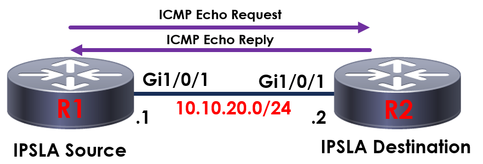
In the topology above, we’ll be sending an ICMP echo probe from R1 to S01 to confirm our device is online.
First off, we’ll create our IP SLA task.
We can have multiple IP SLA tasks running on our devices so we’ll assign this as 1.
R1(config-ip-sla)#icmp-echo 10.10.20.10 source-ip 20.10.20.1
R1(config-ip-sla)#frequency 60
R1(config-ip-sla)#exit
We’ll then use icmp-echo to first of all tell R1 which device we want to send the ICMP echo too.
We might have numerous interfaces on our device so we’ll specify the IP address we want to send our ICMP echo from with the source-ip.
Following this, we need to instruct R1 how often to send the ICMP echo to 10.10.20.10. This is done via the frequency command. The time specified is in seconds, so in this example we send an ICMP echo every 60 seconds.
Now our IP SLA has been configured, we need to schedule when we want to run it and for how long for in order to activate it.
R1(config)#ip sla schedule 1 life forever start-time now
We use the ip sla schedule command to complete this. First, we’ll specify our IP SLA process – 1. We have the option to schedule when our IP SLA runs, however in this example we’ll then start our IP SLA now to run forever.
We can confirm the configuration with the following command:
R1#show ip sla configuration 1
IP SLAs, Infrastructure Engine-II.
Entry number: 1
Owner:
Tag:
Type of operation to perform: echo
Target address: 10.10.20.10
Source address: 10.10.20.1
Request size (ARR data portion): 28
Operation timeout (milliseconds): 60000
Type Of Service parameters: 0x0
Verify data: No
Vrf Name:
Schedule:
Operation frequency (seconds): 60
Next Scheduled Start Time: Start Time already passed
Group Scheduled : FALSE
Randomly Scheduled : FALSE
Life (seconds): Forever
Entry Ageout (seconds): never
Recurring (Starting Everyday): FALSE
Status of entry (SNMP RowStatus): Active
Threshold (milliseconds): 5000
Distribution Statistics:
Number of statistic hours kept: 2
Number of statistic distribution buckets kept: 1
Statistic distribution interval (milliseconds): 20
History Statistics:
Number of history Lives kept: 0
Number of history Buckets kept: 15
History Filter Type: None
Enhanced History:
We can confirm then confirm our IP SLA is running and operating correctly using the following command:
R1#show ip sla statistics 1
Round Trip Time (RTT) for Index 1
Type of operation: icmp-echo
Latest RTT: 1 ms
Latest operation start time: .19:14:37.450 UTC Mon May 25 2020
Latest operation return code: OK
Number of successes: 51
Number of failures: 0
Operation time to live: Forever
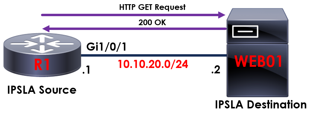
Using our example from before, this time we’ll be using a HTTP GET probe to confirm the status of our internal webpage. Using R1 we want to confirm that our webpage hosted on WEB01 is loading and online.
R1#configure terminal
R1(config)#ip sla 10
R1(config-ip-sla)#http get http://10.10.20.2
R1(config-ip-sla-http)#frequency 60
R1(config-ip-sla-http)#exit
As you can see, this time our command has changed slightly. We use the http get command to inform R1 which page we want to send HTTP GET probes too – in this case it’s 192.168.1.x. Again, we’ll send these probes every 60 seconds using the frequency command.
R1#show ip sla configuration 10
IP SLAs, Infrastructure Engine-II.
Entry number: 10
Owner:
Tag:
Type of operation to perform: http
Target address/Source address: 10.10.20.2/0.0.0.0
Target port/Source port: 80/0
Operation timeout (milliseconds): 60000
Type Of Service parameters: 0x0
HTTP Operation: get
HTTP Server Version: 1.0
URL: http://10.10.20.2
Proxy:
Raw String(s):
Cache Control: enable
Schedule:
Operation frequency (seconds): 60
Next Scheduled Start Time: Start Time already passed
Group Scheduled : FALSE
Randomly Scheduled : FALSE
Life (seconds): Forever
Entry Ageout (seconds): never
Recurring (Starting Everyday): FALSE
Status of entry (SNMP RowStatus): Active
Threshold (milliseconds): 5000
Distribution Statistics:
Number of statistic hours kept: 2
Number of statistic distribution buckets kept: 1
Statistic distribution interval (milliseconds): 20
History Statistics:
Number of history Lives kept: 0
Number of history Buckets kept: 15
History Filter Type: None
R1#show ip sla statistics 10
Round Trip Time (RTT) for Index 10
Type of operation: http:
Latest RTT: 6 ms
Latest operation start time: .21:38:15.563 UTC Mon May 25 2020
Latest operation return code: OK
Latest DNS RTT: 0 ms
Latest TCP Connection RTT: 3 ms
Latest HTTP Transaction RTT: 3 ms
Number of successes: 3
Number of failures: 0
Operation time to live: Forever